We have created our board and it's time to solder the parts on it. I started soldering the pin headers, because they create "blocks" on the board and i could easier point out where to pick the other components.
 |
| large pin headers (1) |
First of all solder the pololu's pin headers. I soldered the Arduino's ones (photo n.4 ) but this wasn't so good in the end that i had to solder top wires and some components near those pins. On the second photo (2) you can see that more pin headers, the smaller ones are soldered on the board. It doesn't matter if you solder pins or resistances for example first.
 |
| smaller pin headers (2) |
Notice: You must have in mind the next things you are about to solder on the board in the "neighborhood". In order to have some extra space for your own convenience.
 |
| snapshot (3) |
Above, snapshot while i go on soldering. It's not so hard, but i am not the perfect as you can see in the bootom of the PCB. The pcb at this stage is finished with the small parts. Just missing the screw terminals for the motots and the Arduino's pin headers.
Arduino's pin headers are a bit tricky because we have one layer pcb, which means we have to solder them from the same side which the copper is. Check put at next photo. The reason i soldered those pins first, was to check that the PCB "locks" on the Arduino. I was anxious about it :)
 |
| Arduino's pins (4) |
Notice: You can check this "lock" without soldering. Pick the pins, the male ones and put them into Arduino. Then take the PCB and put it above. It may not fit well but the headers are not also soldered. If it seems to be very tough then re-mill the PCB. I got something like that without pushing to the end the PCB.
 |
| PCB and Arduino (5) |
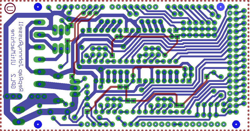 |
| top wires (6) |
After finishing with the bottom side, check at this file the extra top wires. They are noted in red color and are about 10 to 11. You will need to be delicate, otherwise solder them, while you are soldering the others parts.
 |
| almost ended RAMPS v1.2 (7) |
An almost finished RAMPS v1.2 board, I'm still waiting the pololu drives and waiting to see if i will put the diode.
The biggest part of the job has been if reach at this point. But the greatest thing is to test it :)
Also
NOTICE: Check for short-circuits!!!!!
You can check at the end, or after finishing a block of parts. Don't forget it!
P.S. Feel free to comment and ask for extra descriptions i may have omitted.
 |
| the lab :) |


